Inquiry
Inquiry cart car is empty.
High-Performance Testing Instruments Ensure LED Lighting Products Meet Industry Standards
Manufacturers and users of LED lighting applications must ensure that their products comply with various reliability and efficiency standards. In addition to voluntary initiatives and programs such as EnergyStar, mandatory standards and regulations in the lighting industry, including the latest IES LM-79-19 and ANSI C82.16 documents, must also be considered during the development process.
This article provides an overview of the relevant lighting standards and regulations for LED lighting products. It also introduces the features of testing equipment, including the PA900 Power Analyzer (with built-in lighting specifications), DC electronic loads, and hipot testers. These portable testing devices, equipped with touchscreens and other user-friendly features, enable engineers and technicians to easily verify that their LED lighting products meet the necessary parameters for performance, energy efficiency, validation, and safety before being sent to testing facilities.
IES LM-79-19 Standards and Specifications – Solid-State Lighting (SSL)
The Illuminating Engineering Society (IES) updated its LM-79-19 standard for solid-state lighting applications in 2019, marking the first update since 2008. In addition to specifying optical measurements (lumens, chromaticity, luminous flux, etc.), LM-79-19 includes stringent system efficacy requirements. For LED lighting applications, the relevant parameters fall under the "AC Power Standards" (Sections 5.1–5.3), which include:
In the updated 2019 LM-79 standard, the power specifications have been raised from a k=1 to a k=2 confidence interval. This means that during calibration, the measuring equipment must achieve a k=2 confidence level, ensuring 95% accuracy within two standard deviations of the mean.
System efficiency (lumens/watt (lm/W), driver efficiency if not integrated)
Physical and environmental factors (temperature, vibration, airflow, etc.)
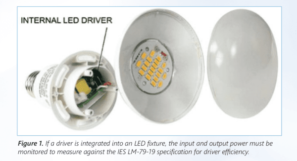
As shown in Figure 1, an LED driver can be integrated into the LED lighting fixture itself. In such cases, testing instruments must measure the input power delivered to the LED driver (power supply) and its output power to calculate system efficiency (Figure 1).
ANSI C82.16-15 Standards and Specifications – LED Drivers
The American National Standards Institute (ANSI) updated the C82.16-15 standard in 2015, establishing mandatory methods and measurements for LED driver input and output parameters. These include:
International Standards for Compliance Testing
The International Electrotechnical Commission (IEC) provides a collection of internationally agreed-upon rules, specifications, and terminology that allow manufacturers to conduct compliance testing on their equipment. (The Vitrek PA9xx series power analyzers include built-in EN50564 specifications for standby power and harmonics, which will be discussed later.) The following standards are relevant to testing LED lighting systems:
Power consumption testing:
The EN50564:2011 standard, which replaces IEC62301, specifies testing procedures for low-power devices and provides guidance for measurement equipment such as power analyzers used in such tests. It outlines how to test products with power supply voltages ranging from 100V to 250V AC and may also apply to three-phase equipment. This standard can be combined with others measuring energy efficiency, such as EnergyStar and the EU Standby Power Directive.
Harmonics testing:
Testing Instruments for LED Lighting Products
As outlined in the previous sections, the industry standards for LED lighting products cover parameters in the following four areas. To ensure that products ultimately pass UL, TUV, Intertek, and SA testing, engineers and technicians should analyze these parameters at every stage of product development.
Performance parameters (design stage):
Energy efficiency parameters (design/production stage):
Validation parameters (production stage):
VASTi Technologies test and measurement equipment has a proven track record in the lighting industry. The equipment described below is used to test LED lighting applications for performance, energy efficiency, verification, and safety parameters required for testing and certification.
Vitrek PA920/PA910/PA900 Power Analyzers
Vitrek's PA9xx series power analyzers measure performance, energy efficiency, and verification parameters of LED lighting products during the design, production, and validation phases of device development. The compact and lightweight PA9xx devices are easy to operate and compliant with the updated LM-79-19 specification, meeting its higher K-2 accuracy requirements.
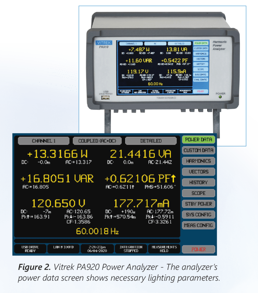
The power data screen of the power analyzer (Figure 2) allows users to easily check if an LED application meets all required specifications by displaying parameters such as voltage, current (ripple), power, apparent power (VA), reactive power (VAR), power factor (PF), frequency, and efficiency.
LED Driver Efficiency Measurement
Vitrek power analyzers can be optionally configured with one to four channels to function as a Virtual Power Analyzer (VPA). By providing the ability to integrate separate power analyzers into the same instrument, the device essentially turns each channel into a separate PA channel.
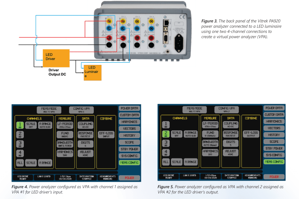
In the following example (Figure 3), the PA is connected to an LED fixture to test LED driver efficiency and ensure the product meets compliance specifications. The rear panel of the power analyzer in Figure 3 shows two channels. At the LED driver end, the input to the LED driver is a 120V AC input signal, and the output is a DC signal (typically around 10 volts).
As shown, the 120V input power (red and black wires) is wired and connected as voltage channel 1. On the current side, the input current is routed to the power meter and returned (blue) to the input side of the LED driver. Therefore, voltage and current are on channel 1. The output of the LED driver, the red/black connection for voltage, is connected to channel 2. For testing, the LED driver output current runs to channel 2 of the power analyzer and exits. It is then connected to the LED fixture.
With the power analyzer and LED driver connected to two channels, the PA's touchscreen panel is used to measure and display the LED driver's efficiency. As shown in Figure 4, the input of the LED driver (top right corner of the panel) is assigned as input number 1 (purple square "Config VPA, VPA1"). This depicts the input of the LED driver to display efficiency, as shown in the purple square on the right under "EFF/LOSS."
As shown in Figure 5, the output of the LED driver is assigned to channel 2, displayed as "CONFIG VPA2" in the top right corner (purple square).
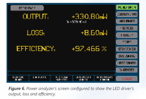
The device is configured to display different parameters by switching between display screens. The PA9xx can easily calculate the output/input power of the LED driver by displaying output, loss, and driver efficiency, as highlighted in yellow in Figure 6.
Compliance Testing – Standby Power
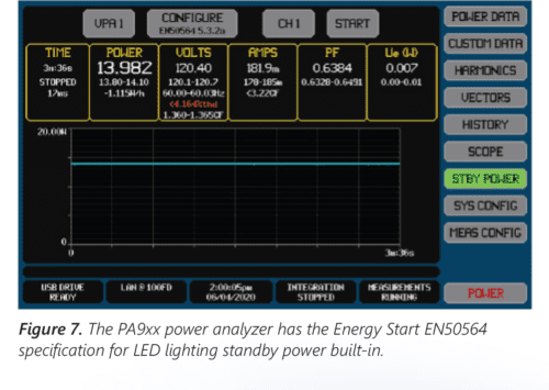
To simplify LED lighting compliance testing, the Vitrek PA9xx series power analyzers feature partial standby power testing compliant with the Energy Star EN50564:2011 5.3.2a specification (Figure 7). In this example, the analyzer is connected to a smart LED lighting fixture. The user can touch the standby power button (right side, green), tap the power button (bottom, red), and press start to see the standby power displayed on the screen (volts, etc.).
In smart lighting applications, measuring standby power can involve turning off the light fixture itself while continuously monitoring its electronics for communication via the internet or an application. In this case, the PA9xx can also be used to measure standby power.
Compliance Testing — Harmonics
Similar to the standby power feature, the PA9xx series power analyzers also have built-in harmonic specifications for AEN61000-3-2 and 4-7. It allows users to select the classification for EN61000 3-2 display (Figure 8). As shown in Figure 9, a red "tick" mark on the harmonics screen indicates that the LED lighting device has failed the harmonic test for the required Class A harmonic levels. The harmonics screen of the PA920, PA910, or PA900 power analyzer can display up to 500 harmonics at a time, even at aviation frequencies.
Other features include:
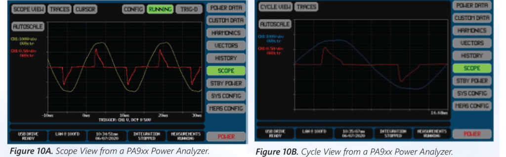
It also provides oscilloscope mode and period mode screens to display ripple and period when calculating LED lighting measurements, as shown in Figures 10a and 10b.
Electronic Loads
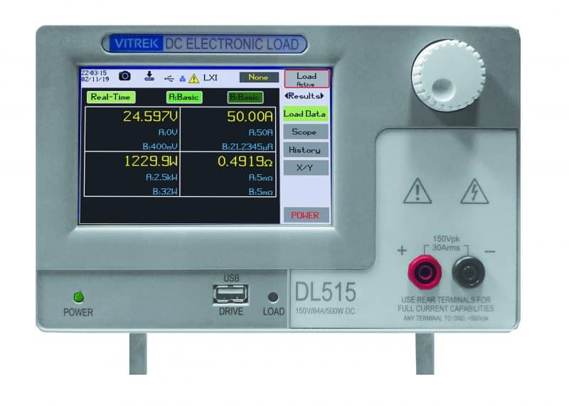
Vitrek's DL Series electronic DC loads are used during the design and production development phases of a project to check the performance and energy efficiency parameters of LED lighting. The LED driver is the power supply for LED lighting applications and needs to maintain a constant current, even as the load increases. Vitrek's programmable DC loads (Figure 11) are compact and portable and can be used where LED applications are installed to detect whether the current is stable and whether the luminous intensity (luminous flux) remains within a reasonable range even when the load changes. The DL series electronic DC loads are available in six different models with three different voltage and power ratings.
Hipot and Ground Bond Testers
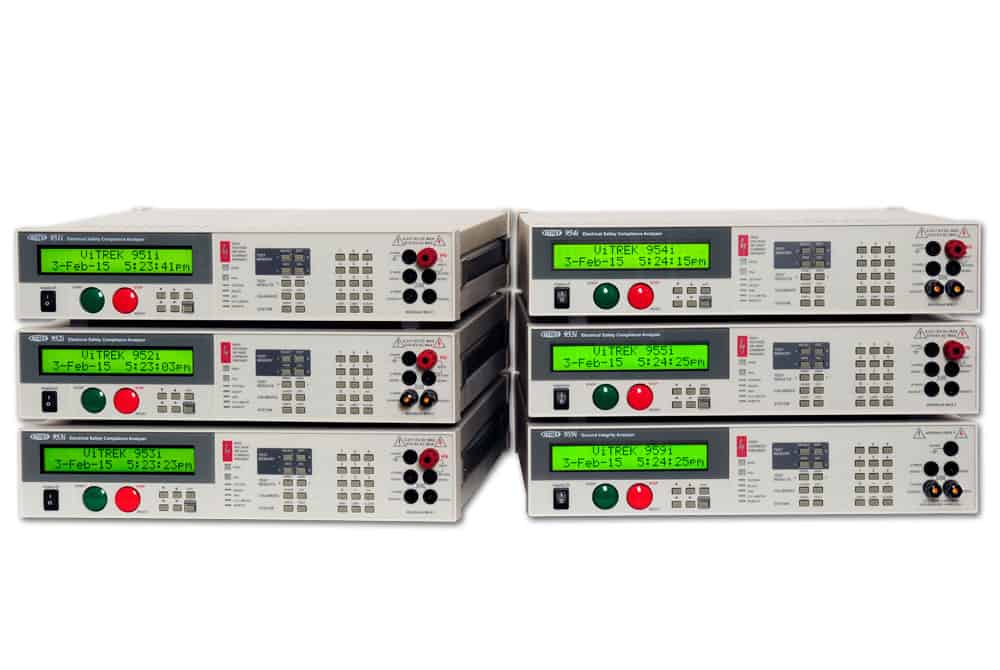
Vitrek's hipot testers (V7x Series and 95x Series) can be used during the final production testing phase to ensure that LED lighting products pass safety certification tests.
Different hipot tester models perform various tests depending on the series, including AC hipot, DC hipot, and insulation resistance, continuity, and ground bond.
The V7x series can directly test 5KV AC and 5KV DC from the front panel. The 95x series can directly test 6KV AC and 6KV DC from the front panel. The 95x series hipot testers offer higher accuracy, speed, and current. External options are available for AC side testing up to 30KV and DC testing up to 15KV.
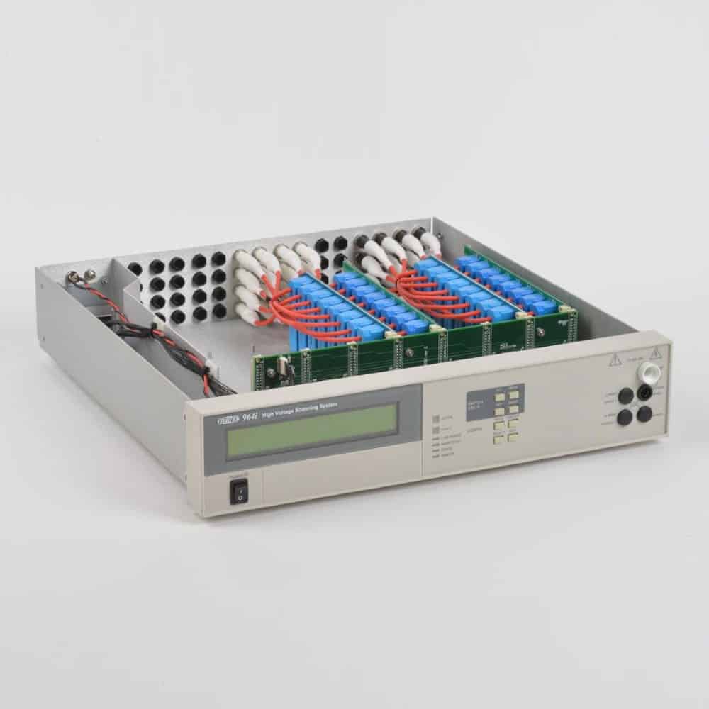
High Voltage Switching Systems
Vitrek's 964i high voltage switching system can be used with Vitrek V7x and 95x series high voltage testers during the final testing phase of product production.
For example, on a production line for manufacturing LED drivers, 10 Vitrek hipot testers can simultaneously test up to 10 LED drivers.
Alternatively, one Vitrek hipot tester can be used with the 964i high voltage switching system to test all 10 LED drivers. In this case, the switch introduces voltage from one high voltage tester to the front panel. A series of relays, which will withstand the high voltage and switch it to multiple points, so 10 relays can switch from relay 1 to 10 to very quickly test 10 different LED drivers.
In addition, when used in conjunction with QT Enterprise software, the 964i switching system can be configured simultaneously with the hipot tester, and the results can be saved for customer audits or requests.
Conclusion
Manufacturers and engineers face the challenge of ensuring that their LED lighting products meet industry standards to pass UL, CSA, TUV, Intertek, and other specifications. As described in this article, Vitrek offers portable, easy-to-use equipment ideal for LED lighting testing at every stage of product development.