Inquiry
Inquiry cart car is empty.
In general, it is also possible to measure very low currents with our current transducers. The accuracy specifications can be found in the data sheet.

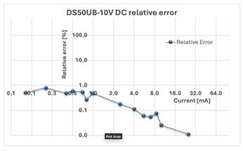
Here you can calculate the total error for very small currents as well. The overall accuracy of the DS50UB-10V is shown below.
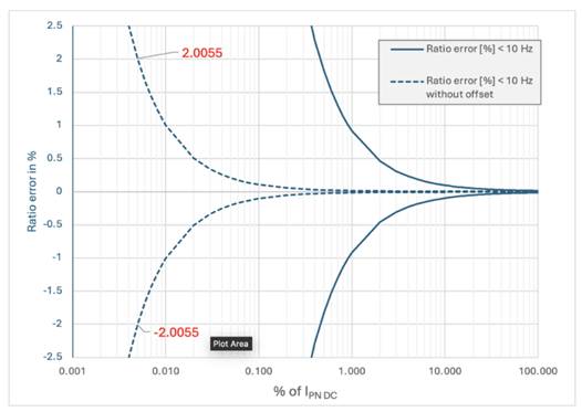
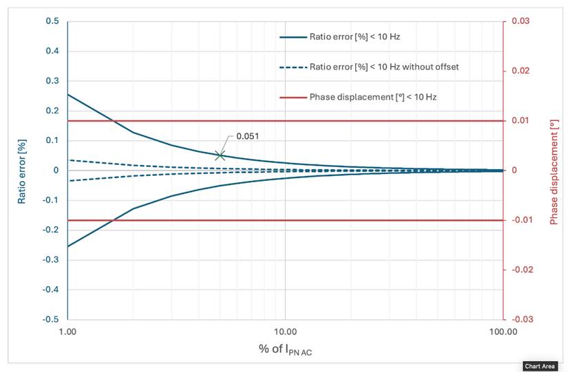
The highest possible accuracy can be achieved if the DC offset of the current transducer is compensated for in the measuring device. The curves with dashed lines show the accuracy without DC offset. The accuracy at 2.5 mA primary current (0.005% of IPN DC) is +-2% for this current transducer. Below you can see test values for the DS50UB-10V without DC offset from ongoing production. These accuracies can only be achieved with professional measuring devices that have appropriate filter options. In this way, noise signals can be eliminated as far as possible.
In particular, if the primary conductor is wound around the current transducer several times, the rapid voltage changes can couple into the current transformer. (manual page 18)
The following measures should be taken to minimize these undesirable effects.
Make sure that the windings around the transducer are evenly distributed (balanced).
Make sure that the loops around the transducer are not too tight.
If possible, measure on the “cold” side of the setup. (Return conductor)
Ground the alu housing of the transducer (Remove the paint on the housing mounting bracket first, manual page 18)
Have a grounded metal tube through the transducer aperture with the winding inside this tube to shield the transducer electronic.
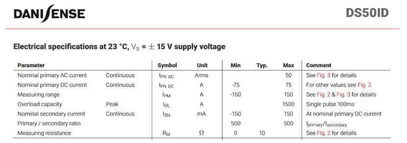
let’s take the DS50ID current transducer as an example. In the data sheet we find the following information.
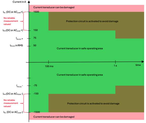
The following figure shows the individual data relating to the primary current. The current transducer may be operated in the green range.
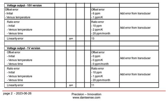
The 1 V module is purely passive with a measuring resistor. The 10 V module, on the other hand, has an active amplifier circuit. For this reason, there is no offset error for the 1 V module, and it can be classified as more accurate in this respect. The ratio error is also slightly smaller than the 10 V module. This data is shown in the datasheet of the interface unit DSSIU-6-1U-V.
https://danisense.com/products/dssiu-6-1u-v/datasheet/
However, electromagnetic interference and a poor signal to noise ratio in the selected measuring instrument can cancel out this advantage.It is therefore up to the customer to weigh up the pros and cons of 1V and 10V output modules for themselves.
All the data for calculating the accuracy of the current transducer is given in the datasheet. The calculation is done for the DS200UB-10V.
If you have a mixed signal the accuracy should be calculated for every frequency component. In this example we will calculate the accuracy for DC signal. Therefore, we use the accuracy data which is specified for the frequency below 10 Hz (<10 Hz). The total ratio error can be calculated by the following equation.
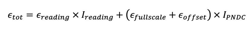
This formula is mentioned in the datasheet on page 3.
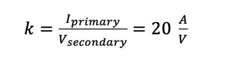
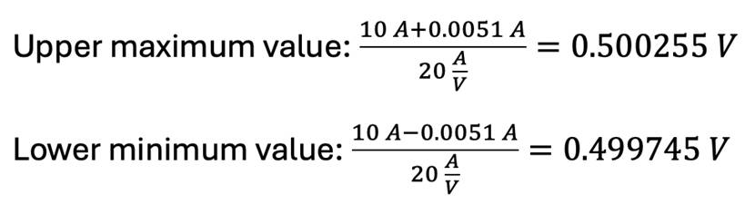
If we now calculate the accuracy of the amplitude for 10 A the equation is as follows.

If you measure 10 A primary current and your measuring device has taken into account the current transducer’s transfer ratio
you get a secondary voltage of
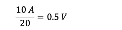
if you have an ideal current transducer without any amplitude error. But we have calculated an ![]() . This means that your measuring device shows a voltage between the following calculated values.
. This means that your measuring device shows a voltage between the following calculated values.
The percentage amplitude error at the instantaneous value of 10 A can be calculated as follows.
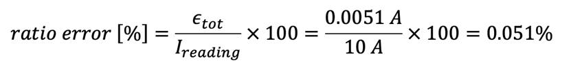
The ratio error can be decreased by compensating the offset error.
The ratio error can now be calculated for any primary current. Even for very small values. Please note that the ratio error increases for smaller primary currents.
The phase displacement is specified in the datasheet for frequency components below 10 Hz with 0.01 °.
Graphically, this results in the following diagram.
This depends on the resolution m in bits of your Analog Digital Converter – ADC. This determines the number of steps M which can be calculated with  . The value of one step (least significant bit – LSB) is a parameter of the theoretical resolution of the ADC in relation to its analogue output range.
Let us assume, for example, that the measuring range of the signal input for the DS50UB-10V is specified as  . If a DC current of +50 A now flows through the DS50UB-10V, this results in 10 V on the secondary side of the current transducer The transformation ratio is defined as V/A = 1/5.
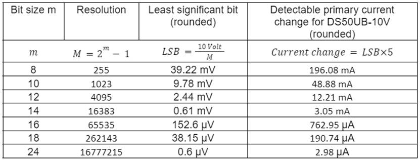
The use of higher-resolution ADCs generally increases the requirements for low-noise components, shielding and grounding concepts. These are therefore mathematical values.
Power analyzers usually use the following basic formula for active power calculation.
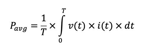
Thus, the digitized instantaneous values of the voltage v(t) and the current i(t) are multiplied together and the results are summed up over a defined time window. Basically, DC components, all harmonic and non-harmonic components up to the bandwidth limit or filter cut-off frequency of the power analyzer are taken into account.
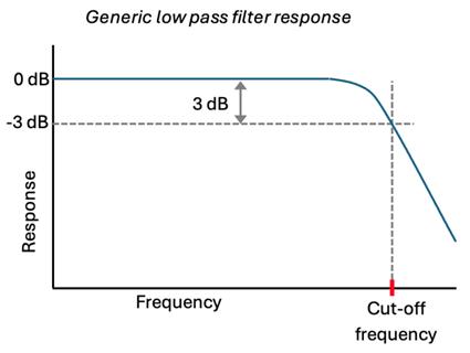
The cut-off frequency of a power analyzer is the frequency characterizing a boundary between a passband and a stopband for the measurement signals which are applied to the input channels. Passband consists of the range of frequencies the filter lets through (minimal attenuation), and the stopband consists of the range of frequencies the filter rejects (high attenuation). The cut-off frequency is sometimes taken to be the point in the filter response where a transition band and passband meet, for example, as defined as the point at which the output level from the filter falls/rises by 50% (i.e., ±3 dB, since a fall/rise of 3 dB corresponds approximately to half power) of the in-band level, assuming a constant input level. It is also sometimes referred to as the half power or ±3 dB frequency.
The stopband of the filter is essentially the band of frequencies that is rejected by the filter. It is taken as starting at the point where the filter reaches its required level of rejection.
The input signals of the measurement channels are damped with -3 dB at the cut-off frequency. All frequency components or noise signals above this cut-off frequency are damped.
Due to the time delay which is generated by the low pass filter all interacting channels should have the same filter characteristics. Otherwise, the internal software of the measurement device has to compensate an additional time delay for a different type of filter.
You need a 50 ohm resistor in the measuring channel that is equal to the characteristic impedance of the coaxial cable if reflections can occur on the connecting cable, i.e. when measuring high-frequency signals or steep-flanked pulses.
Without such a termination at one or both ends of the cable, a reflected wave can run back and forth several times in the cable. The measurement signal can be severely distorted in this way.
It is generally recommended to use high-impedance inputs from 1 Mohm for voltage signals. The unwanted current flow through a high-impedance resistor in the measuring device is kept very low, which reduces negative effects on our specified accuracy.
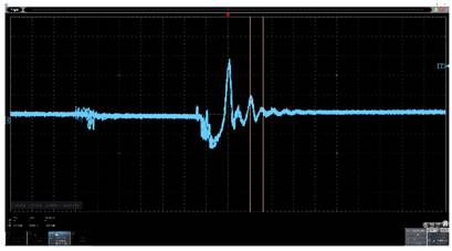
Nowadays, non-linear loads such as switching power supplies not only cause harmonic distortions in the power grid but are often also responsible for electromagnetic radiation. For example, magnetic stray fields are generated by winding components and electrical stray fields by conductors with high pulse voltages. These fields can couple into the current transducer. Oscilloscopes can be used to record these oscillations.
With a DS50UB-10V without a power supply connected and an unearthed housing, an oscillation of approx. 44 MHz can be detected via the BNC connection. This oscillation corresponds to a primary current of approx. 20 mA peak to peak. The measurement was carried out on a standard home office desk.
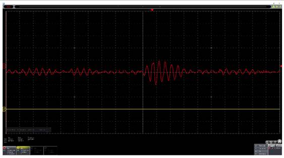
The interference is outside the specified bandwidth of the current transformer of 500 kHz. A low pass filter in the single-digit MHz range could significantly reduce this interference.
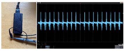
There are always power supply units in use in laboratory setups. In addition to the laptop, measuring equipment such as oscilloscopes also require a power supply unit that converts alternating current into direct current. To keep the internal transformer as small as possible, the mains voltage is inverted into high frequencies. This results in electromagnetic radiation, which can be qualitatively detected with a short-circuited oscilloscope probe, for example.
This radiation can, for example, pass through the inner hole of the current transducer and can therefore be recognized in the secondary signal.
An oscillation at approx. 3.33 MHz can be seen in the image above. The current transducers do not have a low-pass filter at the output, so that these signals are generally not attenuated. For oscilloscope applications, it is recommended to use oscilloscopes that can filter the input signal so that high-frequency interference is minimized.
Yes that is right. Normally the excitation frequency of the current transducer which is specified in the datasheet can be seen. For example, for the DS50UB-10V the excitation frequency is specified with 31.25 kHz. This oscillation is part of the DC supply current.
Outer radius – Inner radius = Distance from the outer housing of the current transducer to the return or neighboring conductor.
Due to the special core design of our current transducers, the fluxgate element which is responsible for detecting the DC current is shielded against electromagnetic fields. Changing the distance to the return conductor affects the accuracy in the ppm range. Maybe 3 times of outer radius would be good for the return. But of course, increasing the distance to the return conductor or other potential disturbance sources is always good.
The Voltage Output Module (VOM) can provide high-precision output signals up to 12 V. If the nominal primary current correlates with 10 V output voltage, an overcurrent of up to 120 % of the nominal primary current can be measured. However, the installed current transducer with current output at the DSSIU-6-1U-V must be specified for this overcurrent.
The 1 V modules only consist of a passive shunt. The output voltage will follow the primary current regarding the specifications of the current transducer with current output.
The inductance of the transducer itself does not contribute that much to the whole primary circuit even above the active range of ~9-10kHz. Customers will probably experience much more inductance from the cabling in the primary circuit.
The reasoning is as follows:
The DCCT operating beyond the active range will act as current transformer and although not entirely zero-flux, the actual flux levels are very low for as long as there is a path for the secondary compensation Ampere-turns to balance the primary A-turns.
We are using high permeability non-gapped cores in the DCCT, so it is not like an inductor wound on a powdered core with distributed air gaps or a ferrite with an intentional air gap to store some magnetic energy.
If several primary windings are used in the respective setup to increase the primary current, the customer can determine the inductance by calculating the primary windings around the Danisense CT as an air-core coil.
In many cases, the specified bandwidth of the current transducer is below the bandwidth of the measuring device. Signal components transmitted to the secondary side above the specified bandwidth of the current transducer can be significantly amplified or attenuated. The bandwidth of the current transformers is not limited by a low pass filter with the corresponding cut-off frequency.
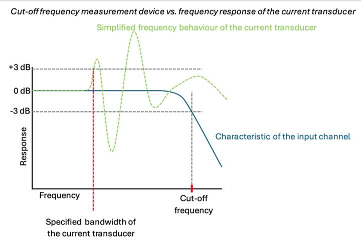
According to the Danisense datasheets all current transducers have a specified bandwidth. The value can be found on page 2.

Interference signals or higher frequency components in the primary signal can be amplified or attenuated by the current transducer in the range between the specified bandwidth of the current transducer and the cut-off frequency, which can falsify the measured values.
This is the expected behavior of the Danisense current transducers. Due to the lack of the power supply, the current transducer can temporarily no longer regulate the magnetic flux density in the magnetic cores towards 0. That’s why those current transducers are also called zero-flux current transducers. If the primary current is not switched off, it continues to generate a magnetic field and therefore a magnetic flux in the iron cores. If the current transducer is put back into operation by plugging in the DSUB cable the green LED stays dark and the device remains in fault. The explanation is that the flux-gate detector is in saturation due to the existence of the primary current before transducer turn-on, so the transducer controls is not able to cancel/nullify the magnetic field inside the core. Consequence can be the larger offset error / magnetization of the core.
In order to achieve the specified error values again, the primary current should only be switched on if the power supply to the current transducer is correct. This is the only way to guarantee that no residual magnetization of the iron cores occurs.
If the DSUB cable is accidentally disconnected from the current transducer during test operation and then reconnected, the primary current must be set to zero. Afterwards the current transducer should then work again as expected.
Yes. On page 22 in the manual the behavior of the fluxgate transducers is well explained on page 22. The current sensor will then work correctly again.
In general, you can increase the ohmic resistance if you measure small primary currents. In most of the datasheets you can find the figure 2.
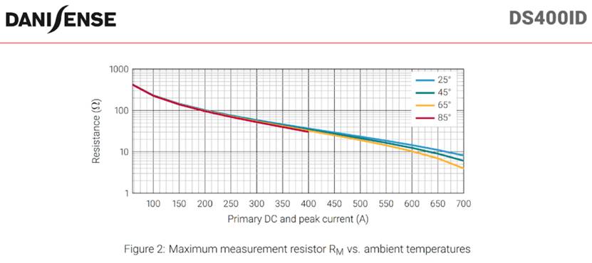
If the primary current rises while using a high ohmic burden resistor, the voltage across the burden resistor will increase and at some point, the relay in the transducer will switch off the transducer to off.
The mechanism is that when we reach the high voltage on the burden resistor close to the DCCT supply voltage, the operational amplifier in the DCCT cannot source more current and the magnetic core will exit zero-flux operation i.e. the flux gate detector will saturate. This will cause the relay to turn off the transducer output. The transducer should not be damaged.
This is the expected behavior of the current transducer. The reason is to keep the offset error of the transducer within the specification.
The fluxgate detector is in saturation and cannot control the compensation current, so relay contacts are closed and shorting the winding to protect electronics.
Reference: https://danisense.com/faq/
This article is published under the authorization of Danisense. The Chinese translation rights are held by VASTi Technologies co, ltd. All rights reserved.